Views: 5 Author: May 26, 2020 by Charles Kolstad Publish Time: 2025-07-08 Origin: https://tameson.com/pages/hydraulic-solenoid-valve


Hydraulic directional control valves are represented by the number of ports and switching positions. For example, a 4/3-way hydraulic valve has four ports and three positions (Figure 2). These valves are designed to handle high-pressure applications, with a maximum pressure rating of up to 350 bar (5075 psi), making them suitable for demanding environments.
The different components are:
DIN connector (B): DIN connectors' primary role is as the interface between the valve and the power supply. These connectors have various other functions that improve the solenoid valve's functionality. For more information, read our article on DIN connectors.
Solenoid (C): When the solenoid is powered, the spool moves towards it, changing which ports are open and which are closed.
Spring return (D): The spring return ensures that the spool returns to its default position when the solenoid is not powered.
Control spool (E): The spool is a cylindrical component inside the valve that moves to direct the flow of hydraulic fluid.
Ports (T, A, P, B): Hydraulic fluid enters and exits through the ports.
Pressure port (P): This is where the hydraulic fluid enters the valve under pressure from the pump. It supplies the fluid that will be directed to the working ports.
Working ports (A and B): These ports connect to the hydraulic actuator, cylinder, or motor. Depending on the spool position, fluid is directed to port A or B to perform work, such as extending or retracting a cylinder.
Return port (T): This port allows hydraulic fluid to return to the reservoir after passing through the system. It helps maintain the fluid circuit and ensures that excess fluid is safely returned.
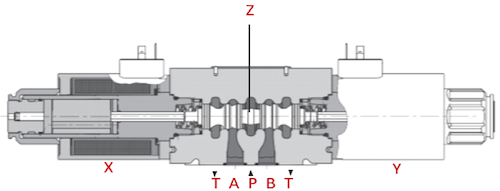
Figure 2: Hydraulic solenoid valve diagram. Components of a 4/3-way hydraulic solenoid valve: manual override (A), DIN connector (B), solenoid (C), spring return (D), and control spool (E). Also, ports A, T, B, and P.
4/3-way and 4/2-way solenoid valves for hydraulic applications can have a single or double solenoid design and be configured in a normally open or normally closed position.
In a single solenoid valve, the spool shifts when activated, and a spring automatically returns it to its original position once the solenoid is de-energized.
A double solenoid valve allows the spool to shift right or left depending on which solenoid is energized. 4/3-way valves return to the center position when de-energized unless they have a latching or detent mechanism (see below).
Whether or not to get a single or double-solenoid valve depends on whether or not you need to consider the unenergized state. Choose a single-solenoid valve if you always want the valve to be in the same state when it's unenergized.
It's crucial to ensure that only one solenoid is energized at any given time to maintain proper function and avoid potential issues.
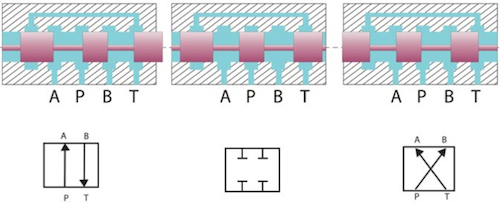
Figure 3: Working principle of 4/3-way solenoid valve
The spool inside the 4/3-way hydraulic solenoid valve can shift into three different positions, each altering the flow path of the fluid:
Position 1 (Figure 3, top): When the spool moves to the right, port P connects to port A, and port B connects to port T. This configuration directs fluid from the pressure port to one working port while the other working port returns fluid to the reservoir.
Position 2 (Figure 3, center): In this closed-center position, all ports are blocked. This stops fluid flow, allowing the system to maintain pressure without movement.
Position 3 (Figure 3, bottom): When the spool shifts to the left, port P connects to port B, and port A connects to port T. This reverses the flow direction, sending fluid to the opposite working port and returning fluid from the other port to the reservoir.
Four ports: The valve includes a pressure port (P), two working ports (A and B), and a return port (T).
Two positions: The spool inside the valve can shift into two different positions, each altering the flow path of the fluid:
Position 1 (Figure 4 top): In this position, the pressure port (P) connects to working port (A), and working port (B) connects to the return port (T). This configuration directs fluid from the pressure port to one working port, allowing the actuator to move in one direction.
Position 2 (Figure 4 bottom): When the spool shifts to the other position, the pressure port (P) connects to working port (B), and working port (A) connects to the return port (T). This reverses the flow direction, sending fluid to the opposite working port and allowing the actuator to move in the opposite direction.
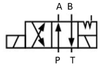
Figure 4: Working principle of 4/2-way solenoid valve
Some double solenoid valves have a detent mechanism that allows the user to decide which position is the default. A detent mechanism is a mechanical feature that holds the spool in place. Because they are mechanical, detent mechanisms are more robust than latching mechanisms.
When the valve is energized, the detent releases the spool, allowing it to switch to the other position. Therefore, an operator can decide the default state of a hydraulic solenoid valve.
Similarly, in a 3-position valve, the detent mechanism can hold the spool in any of its three possible positions. This allows the valve to maintain a specific state without continuous power, which can be helpful for energy efficiency and maintaining system stability.
The function of a hydraulic solenoid valve refers to its default position. The following default positions are available:
All ports open: This position can be used to equalize pressure.
All ports closed: This position can be used to maintain the hydraulic actuator's position.
P open to A, B open to T: The spool directs fluid from the pressure port (P) to one working port (A). The other working port (B) returns fluid to the reservoir (T).
P open to T, A and B closed: This position can relieve pressure in the system by bypassing the working ports and returning fluid to the reservoir.
Detent (no default position): The detent allows the user to decide the valve's default position.
P closed, A and B open to T: This position allows any fluid remaining in the hydraulic actuators to return to the reservoir.
P open to B, A open to T: The spool directs fluid from the pressure port (P) to one working port (B). The other working port (A) returns fluid to the reservoir (T).
When choosing between 4/3-way and 4/2-way hydraulic solenoid valves, consider the following:
4/3-way valve: 4/3-way valve is typically used for applications requiring a neutral position where the actuator can be held, float, or have pressure relieved. It's ideal for more complex control where intermediate positions are needed.
4/2-way valve: A 4/2-way valve is suitable for simpler applications where the actuator must switch directly between two states, such as extending and retracting a cylinder without an intermediate position. It is ideal for straightforward on/off control.
High pressure: Because hydraulic solenoid valves operate in hydraulic systems, they must withstand high pressures. These valves can handle pressures up to 350 bar (5076 psi).
Manual override: The manual override allows a user to change the valve's position without power. This is especially useful in the case of a power outage.
The application's flow requirement will help determine the valve's size. To maintain efficient operation and avoid bottlenecks, choose a valve with a flow rate capacity that matches or slightly exceeds your system's requirements. Valves with flow rates of 60 - 80 l/m are commonly used.
Ensure the valve size matches the port dimensions of the existing components. Hydraulic solenoid valves are typically available with connection sizes of NG6 (D03), which indicates a nominal size of 6 millimeters.
Automotive sector: Used in hydraulic motors, braking systems, and pumps to control fluid flow, ensuring efficient vehicle operation.
Power generation: Regulates fluid flow in turbine systems to optimize performance and maintain safety in power plants.
Manufacturing and processing: Controls the flow of liquids and gasses in production processes, enhancing automation and efficiency.
Gas and fuel supply: Controls the flow of gas and fuel in distribution and processing, providing safety and efficiency.
Agricultural machinery: Used to control implements and attachments, improving the efficiency and precision of farming equipment.


